- 您现在的位置:买卖IC网 > Sheet目录1236 > PI2211-EVAL1 (Vicor Corporation)BOARD EVAL FOR PI2211
�� �
�
�?� ?� ??�
�For� example:� A� MOSFET� with� a� R� θ� J-C� of� 2.5°C/W,� a� BUS�
�voltage� of� 12V,� and� a� start-up� current� limit� of� 6.25A� will� yield�
�the� following� R� θ� J-C� scaling� factor:�
�Using� the� thermal� impedance� curves� shown� in� Figure� 16� and�
�a� R� θ� J-C� scalar� of� 0.32,� the� intersection� with� the� single� pulse�
�curve� produces� a� pulse� width� of� 1.4ms.� To� summarize,� a�
�1.4ms� pulse� of� 75W� across� this� particular� MOSFET� should�
�raise� the� junction� to� case� temperature� by� 60°C.�
�Knowing� the� pulse� width,� Tau� P� can� be� calculated� using� the�
�equation� below:�
�Where;� PULSE� is� the� pulse� width� taken� from� the� R� θ� J-C� thermal�
�impedance� curves,�
�R� θ� C-A� is� the� default� junction� to� case� thermal�
�impedance� of� 60°C/W,�
�R� θ� J-C� is� the� maximum� junction-to-case� value� of� the�
�MOSFET� scaled� by� the� ratio� of� the� FET's� R� θ� C-A� and� the�
�default� R� θ� C-A� .�
�Power� is� the� nominal� BUS� voltage� multiplied� by� the�
�current� programmed� via� R� SOAS� .�
�Power� =� BUS� *� R� SOAS� *� .0025�
�The� power� across� the� MOSFET� is� calculated� by� the� PI2211� as�
�the� product� of� the� BUS� voltage� and� the� programmed� current�
�as� determined� by� R� SOAS� .�
�Knowing� Tau� P� ,� R� SOAT� can� be� calculated� using� the� equation�
�below:�
�?�
�PI2211�
�??�
�longer� to� reach� their� normalized� value,� even� though� they�
�might� be� in� the� same� package.� As� this� single� pulse� time�
�increases,� then� effect� of� the� R� θ� J-A� will� become� more� dominate�
�and� the� R� θ� J-A� single-pulse� thermal� impedance� curve� should� be�
�used� to� determine� the� pulse� width� for� a� 60°C� junction� rise.�
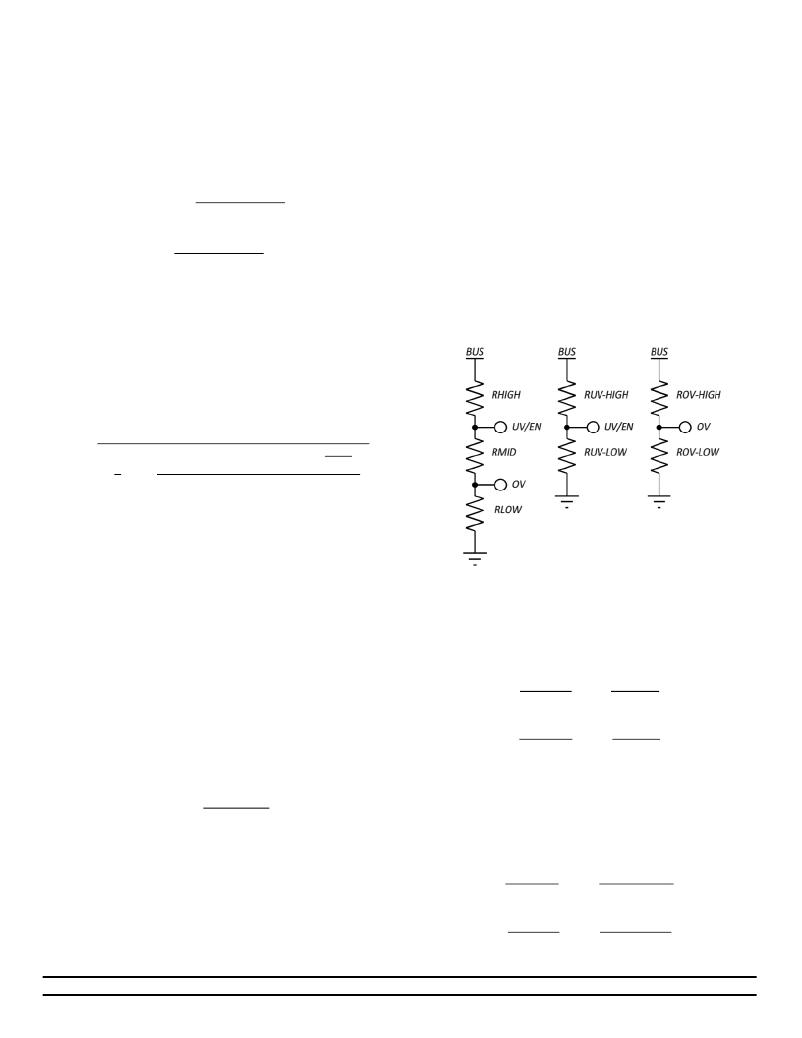
�4)� Under� and� Over-Voltage� Programming:�
�As� is� shown� in� Figure� 7,� there� is� a� programmable� window� of�
�BUS� voltage� range� where� the� PI2211� is� guaranteed� to� be�
�operational.� This� window� is� defined� by� the� OV� pin� voltage�
�being� ≤� 0.675Vdc� and� the� UV/EN� pin� voltage� being� ≥�
�0.750Vdc.� The� user� should� be� aware� that� VBUS� MAX� ,� when�
�calculated� using� the� following� equations,� is� the� maximum�
�voltage� where� the� controller� is� guaranteed� to� be� operational,�
�not� the� maximum� voltage� where� the� controller� faults.�
�Figure� 17� -� Resistor� divider� options� for� UV� and� OV� threshold�
�programming.�
�To� calculate� the� OV� and� UV� resistor� divider� ratios� for� separate�
�networks:�
�Using� a� three� resistor� string� (R� HI� ,� R� MID� ,� R� LO� );� when� VBUS� MIN� the�
�voltage� on� UV� is� 0.75V,� when� VBUS� MAX� the� voltage� on� OV� is�
�0.675V.� The� ratio� of� the� R� MID� to� R� LOW� can� be� determined� once�
�the� ratio� of� VBUS� MAX� to� VBUS� MIN� is� set.�
�Using� junction-to-case� thermal� impedance� curves� is� a� good�
�method� to� determine� the� duration� of� the� power� pulse� since�
�the� junction-to-case� heats� up� much� faster� than� the� case-to-�
�ambient� and� they� are� typically� the� most� accurate� thermal�
�curves� published.�
�The� MOSFET� in� Figure� 16� reaches� its� normalized� R� θ� J-C� value� at�
�about� 50ms.� MOSFETs� with� larger� die� sizes� can� take� much�
�Picor� Corporation� ·� picorpower.com�
�PI2211�
�Rev� 1.0,� Page� 21� of� 26�
�发布紧急采购,3分钟左右您将得到回复。
相关PDF资料
PI5101-EVAL1
EVALUATION BOARD FOR PI5101
PICOSMDC035S-2
POLYSWITCH PTC RESET .35A 0805
PIIPM25P12B008X
IC PWR MODULE PROG ISO 25A 1200V
PK3020KB
KIT KEYPAD, MOUSE, AND USB HUB
PK3021LI
KIT LIGHT, MOUSE, AND USB HUB
PK3022ET
KIT CAT5 CABLE MOUSE USB HUB
PKSERIAL-I2C1
BOARD DEMO PICKIT SERIAL I2C
PKSERIAL-SPI1
BOARD DEMO PICKIT SERIAL SPI
相关代理商/技术参数
PI223MC-A6
制造商:AMI 制造商全称:AMI 功能描述:200DPI CIS Sensor
PI224MC-A6
制造商:AMI 制造商全称:AMI 功能描述:200DPI CIS Sensor
PI22-5,08
功能描述:可插拔接线端子 PCB Hdr, 45 Deg, 5,08 PitchOpen End, 22pole, 12A,300V,Grn RoHS:否 制造商:Phoenix Contact 产品:Plugs 系列:PTS 端接类型:Spring Cage 位置/触点数量:5 线规量程:26-14 节距:5 mm 电流额定值:10 A 电压额定值:250 V 安装风格: 安装角: 触点电镀:
PI225MC-A6
制造商:AMI 制造商全称:AMI 功能描述:200DPI CIS Sensor
PI226M-A4
制造商:AMI 制造商全称:AMI 功能描述:200DPI CIS Sensor
PI227
制造商:AMI 制造商全称:AMI 功能描述:200DPI CIS Sensor
PI227MC-A4
制造商:AMI 制造商全称:AMI 功能描述:200DPI CIS Sensor
PI228MC-A4
制造商:AMI 制造商全称:AMI 功能描述:200DPI CIS Sensor